SYSTEMS/GLASS AND METAL CURTAIN WALLS
Poured-in-Place
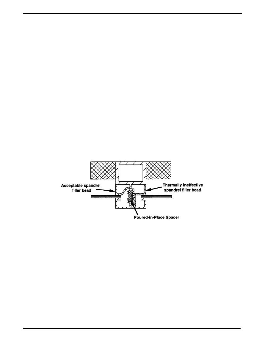
Poured-in-place mullion systems have been widely used in less expensive curtain wall systems for
a long time. These systems employ mullions which are fabricated in the shop. As shown in Figure
4.1.4, the system is based on a poured-in-place spacer which serves as a thermal break as well as
a structural element. A receiver pocket is extruded into the framing system, which later receives a
hot molten plastic. After the plastic is cured, a portion of the metal pocket is machined out to
eliminate the metal-to-metal connection between inside and out. Due to structural considerations,
this system is not recommended for use in "high performance" curtain walls where severe wind
loads are expected. The plastic spacer must transfer all loads applied to the exterior face into the
structural framing. These materials can become brittle in very cold temperatures and soft under hot
temperatures. Thus, material selection is a very important issue. The framing must be designed so
that the plastic filler forms a continuous thermal break. Sometimes spandrel filler beads, shown by
the dashed line in the figure, bridge the thermal break and such designs should be avoided.
Another issue with this system is that many architects prefer only about 60 mm (2 1/2 inches) of
exposed framing, and that is not enough to achieve adequate structural performance. 80 mm (3 1/4
inches) is a preferable minimum dimension.
ACCEPTABLE
Figure 4.1.4 Poured-in-Place Mullion
Screw-on-Face with Snap-On Cover
This is a fairly standard system offered by most curtain wall manufacturers. As shown in Figure
4.1.5, the thermal break is provided by a low-conductivity spacer, usually made of vinyl or rigid
PVC. The design of the spacer is critical in terms of material selection and its long term ability to
seal out water. The exterior extrusions are attached with screws, whose size, type and spacing is
based on structural considerations. In designing these systems, the bridging caused by spandrel
glass adapters must also be reviewed. The figure shows a nonbridging adapter on the left; the
dashed line on the right shows an adapter that conducts heat.
PAGE 4.1-4


 Previous Page
