SYSTEMS/ROOFING
Similar details to those shown above can be developed for other wall systems. Examples of many
such details are given in Brand.
Roof Penetrations
The continuity of the roof vapor retarder, thermal insulation and roofing membrane are inevitably
violated by various penetration including equipment supports and drains. These penetrations can
be the sites of both air and water leakage leading to a variety of problems, including thermal
bridging, air leakage, condensation, and wetted insulation. Penetrations must be carefully designed
and constructed with proper flashing, seals and thermal insulation. Flashing and sealant details for
a variety of penetrations are contained in the NRCA manual. The examples below address
primarily the continuity of the thermal insulation system.
The ORNL catalog of thermal bridges identified three common penetration designs that lead to
thermal bridging and contains improved alternate design details (Steven Winter Associates). The
first thermal bridge is at the penetration of the roof by a steel railing, which interrupts the thermal
insulation, leading to increased heat loss and the potential for condensation. The alternate design
substitutes glass fiber for steel in the railing and its connections to the deck.
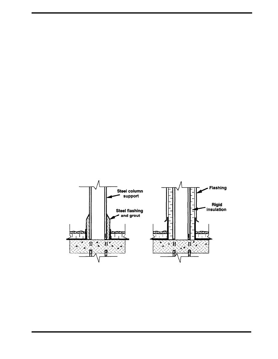
Figure 4.8.10 shows a thermally bridging equipment support consisting of a column that extends
through the insulated roof deck. In the alternative design, insulation is attached to the outside of the
columns to reduce the heat transfer and decrease the condensation potential.
ACCEPTABLE
UNACCEPTABLE
Figure 4.8.10 Heavy Structural Support (Steven Winter Associates)
PAGE 4.9-9


 Previous Page
