SYSTEMS/ROOFING
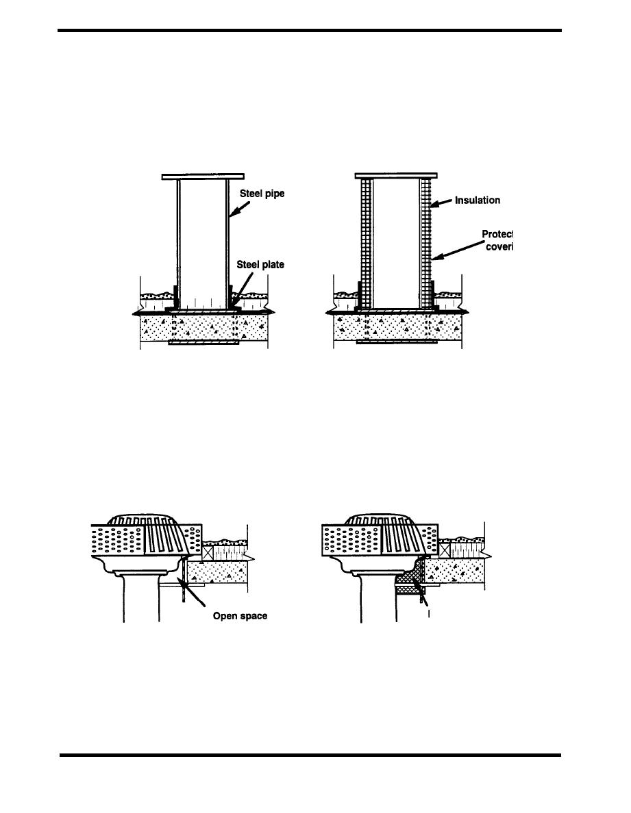
A thermally bridging support for light equipment is shown in Figure 4.8.11. In the base case a steel
support plate is mounted on a steel pipe, acting as a thermal bridge and increasing the
condensation potential. In the alternative design, the outside of the pipe is insulated to reduce the
heat transfer.
ACCEPTABLE
UNACCEPTABLE
tive
ing
Figure 4.8.11 Light Structural Support (Steven Winter Associates)
Figure 4.8.12 shows a roof drain with a severe insulation discontinuity, along with a thermally
improved alternative. In the base detail, the insulation stops far short of the drain and the space
around the hub of the drain is open. The alternate detail includes a thermal break between the
clamp and the slab, and the air space around the hub is filled with insulation.
ACCEPTABLE
UNACCEPTABLE
Fill all voids with
insulation
around drain hub
Figure 4.8.12 Roof Drain
PAGE 4.8-10


 Previous Page
