SYSTEMS/MASONRY
Figure 4.2.3 shows unacceptable and acceptable flashing details at horizontal shelf angle joints. In
the unacceptable case, the flashing is not extended beyond the face of the brick veneer, decreasing
its ability to drain water to the outdoors. In the acceptable detail, the flashing is extended well
beyond the face of the brick and is positively sloped to the outdoors. The flashing must not be
terminated on the shelf angle because that will allow water to drain behind the sealant and into the
cores of the brick veneer. Nor should the flashing be terminated against the inner surface of the
backup wall, since water draining down the cavity will be able to get behind the flashing. Instead,
the flashing must be carried up over the shelf angle and anchored at least 20 mm (8 in.) into the
first course of the inner wythe. The relative positioning of the flashing and the anchor bolt must be
considered to avoid puncturing the flashing. The flashing is sometimes placed in the second
veneer mortar joint above the shelf angle for this reason. A compressible filler (e.g. neoprene) is
placed under the shelf angle to keep debris, especially mortar, out of this space. If mortar does get
under the shelf angle, differential movements result in unacceptable loads being imposed on the
veneer.
ACCEPTABLE
positive slops towards roof
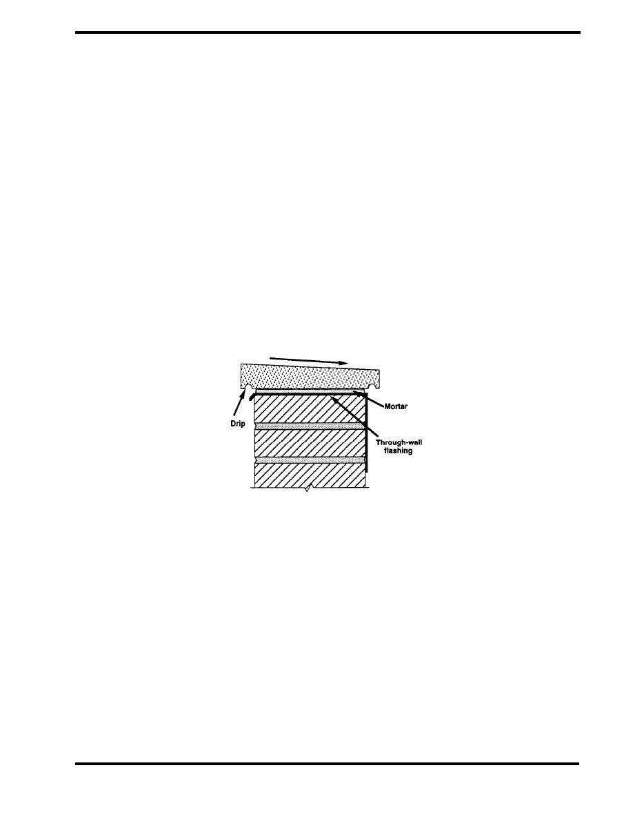
Figure 4.2.4 Flashing at Coping (CMHC)
Parapet flashing is extremely critical because of the exposure of these elements. In order to keep
water out of the parapet and to prevent it from running down into the wall, through-wall flashing is
required below copings and near the base of the parapet. Figure 4.2.4 shows such through-wall
flashing below a pervious or segmental coping. Note that drips are included in the coping on both
sides of the parapet, and that the coping slopes towards the roof to prevent water from running
down the outer facade.
PAGE 4.2-7


 Previous Page
