SYSTEMS/MASONRY
Brick Veneer Walls
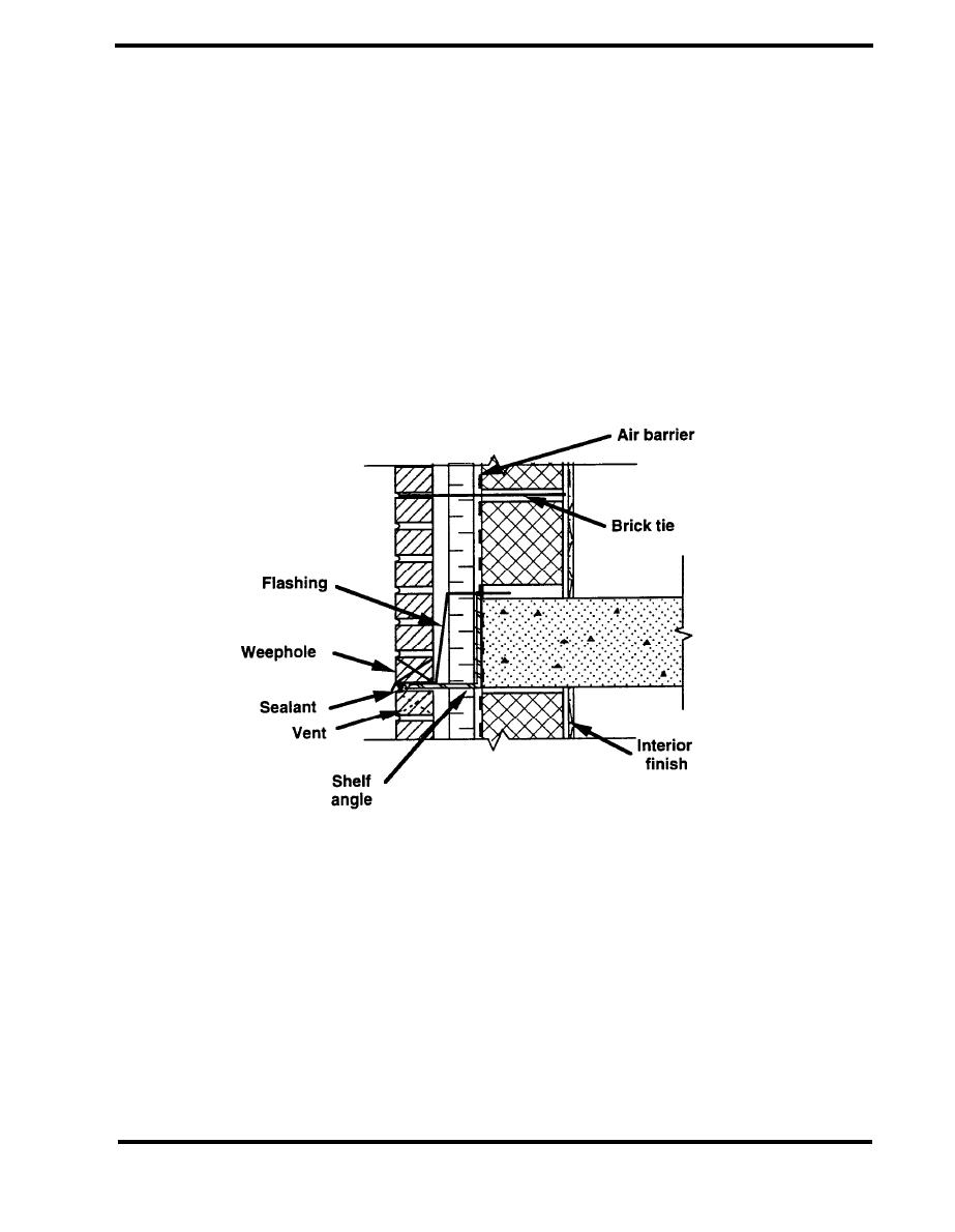
Brick veneer walls employ a two-stage approach to the control of rain penetration. Figure 4.2.1 s a
schematic of a brick veneer wall, showing the major components of the system. In this design
approach, the veneer is intended to shed most of the rain water, at the same time acknowledging
that some water will penetrate into the cavity. The veneer must still be designed and constructed to
provide wind and water resistance so that the water-tightness of the backup wall is not continuously
tested. If the veneer is not at all watertight, then the backup wall really constitutes a single stage
system. The cavity must be flashed at appropriate locations so that any water that does penetrate
the veneer is drained to the outdoors. Ideally, the veneer should serve as a pressure-equalized
rainscreen in which openings in the veneer keep the cavity pressure close to the outdoor pressure,
preventing pressure driven rain penetration into the cavity. These openings must be designed to
limit rain penetration due to capillary and gravity-driven flows. For the pressure-equalized
rainscreen approach to be effective, the backup wall must be airtight.
Figure 4.2.1 Brick Veneer Wall (CMHC 1989)
The design and performance of brick veneer walls is covered in BIA Technical Notes 21 and 21B,
the Canada Mortgage and Housing Corporation (CMHC) Seminar on Brick Veneer Wall Systems,
NCMA-TEK No.62 and No.79, and the PCA Concrete Masonry Handbook. The information in these
documents concentrates on materials, structural issues and water leakage control. BIA 21B
emphasizes structural issues and includes details of anchorage, expansion joints, foundations and
window connections. Except for the CMHC document, design issues related to thermal envelope
integrity are not emphasized in many of these guidance documents.
PAGE 4.2-3


 Previous Page
