SYSTEMS/MASONRY
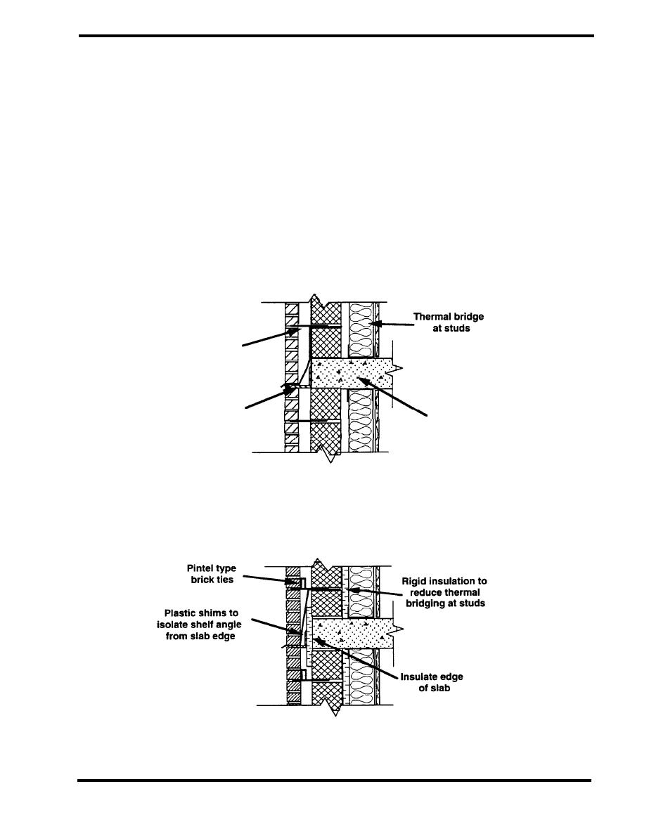
Figure 4.2.13 shows a typical floor/wall connection that suffers from thermal bridging and air
leakage. In this design an insulated stud wall is located inside the masonry backup, and the studs
act as thermal bridges through the insulation. There is no air barrier system in the wall to control air
leakage. The slab bridges the wall insulation, and the shelf angles add to the heat loss effects. In
addition, the "truss" type brick ties serve as an additional thermal bridge between the outside and
the backup. An improved design is shown in Figure 4.2.14. Rigid insulation is added between the
backup and the stud wall to reduce the thermal bridging from the studs. An air barrier is installed on
the exterior side of the backup wall to control air leakage. "Pintel" type ties are used to reduce
thermal bridging. The edge of the slab is insulated to reduce the thermal bridging effect of the slab,
although discontinuities in the insulation system remain. Finally, high density plastic shims are
used at the shelf angles to reduce the thermal bridging at this location.
UNACCEPTABLE
Truss type
brick ties
Shelf angle extends
Floor slab bridges
thermal bridge
wall insulation
Figure 4.2.13 Wall/Floor Connection
ACCEPTABLE
Figure 4.2.14 Wall/Floor Connection
PAGE 4.2-19


 Previous Page
