SYSTEMS/MASONRY
UNACCEPTABLE
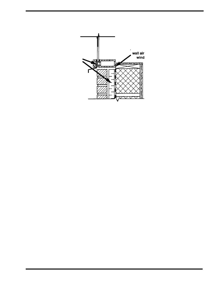
Air leakage between
Wall insulation out
barrier and
of line with mullion
ow frame
thermal break
Figure 4.2.11 Air Leakage at Window/Wall Interface
(Quirouette 1983)
Vapor retarder design for masonry walls must follow the guidance in the section Design/Vapor
Retarders. The vapor retarder need not be absolutely continuous like the air barrier, but it must be
applied to all portions of the envelope. Areas that are sometimes neglected include walls above
suspended ceilings and behind convector cabinets. The position of the vapor retarder within the
wall depends on the climate and the placement of the thermal insulation, and needs to be
considered on a case by case basis as described in the section Design/Vapor Retarder. In some
designs the air barrier is also intended to act as the vapor retarder, and in these cases the same
analysis of vapor transport needs to be conducted.
There are several different options for providing a vapor retarder in terms of location and materials.
The CMHC Seminar on brick veneer wall systems describes options for heating climates. First, the
vapor retarder can be part of the interior finish, a necessity when the insulation is placed inside of
the backup wall. Appropriate materials include oil or alkyd paint over gypsum board, polyethylene
over the insulation, and impermeable insulation itself. If the insulation is positioned in the cavity, the
vapor retarder can be located on the inside face of the backup wall using paint or other vapor
retarding materials. A membrane on the exterior face of the backup wall can also serve as a
combination vapor retarder and air barrier. Self-adhesive and torched-on membrane materials are
effective. Since the membrane is serving as an air barrier, it must be continuous, able to
accommodate movement cracks and remain firmly attached over time despite air and vapor
pressures. When rigid insulation is applied to the external face of the backup wall, the mastic
adhesive will serve as a vapor retarder. To be effective, a full bed of mastic must be applied and
joints between insulation boards must be fully buttered.
PAGE 4.2-15


 Previous Page
