ENVELOPE SYSTEMS/EIFS
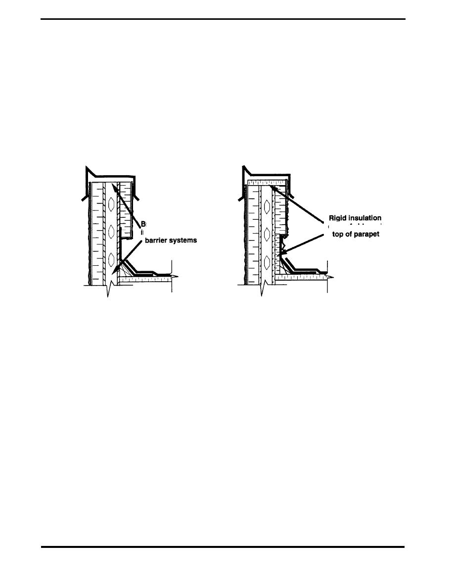
Another parapet design is shown in the Figure 4.7.5. In the unacceptable case, the EIFS cladding
is carried partway down the inner wall of the parapet. This is an improvement over the previous
case, but the thermal bridge caused by the studs remains at the top of the parapet and below the
inner wall's EIFS. In the modified detail, rigid insulation is added at the top of the parapet and to the
inner parapet wall below the EIFS cladding. As in the previous case, the base flashing serves as
an air barrier.
ACCEPTABLE
UNACCEPTABLE
reaks in thermal
on roof side and
nsulation and air
Figure 4.7.5 Thermal Defect at Parapet
PAGE 4.7-6


 Previous Page
