ENVELOPE SYSTEM/EIFS
Selected Design Details
As with all wall systems, the intersections between different envelope components are critical areas
for the maintenance of air barrier and insulation system continuity. This section presents
unacceptable and acceptable design details for several such component intersections.
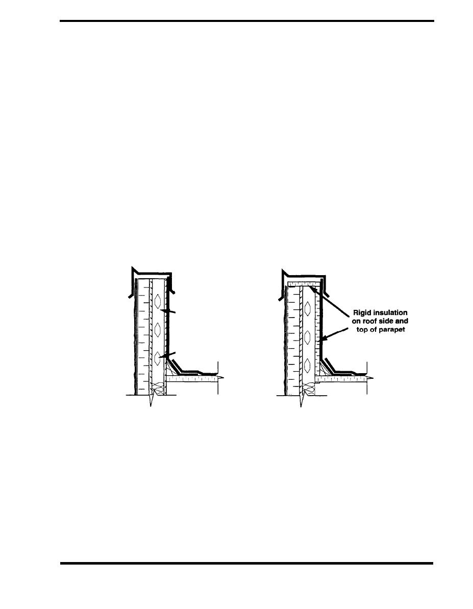
A common roof parapet detail with a metal stud backup wall, is shown in Figure 4.7.4, along with an
improved alternative. In the unacceptable case, insulation is installed between the studs up to the
roof insulation, but the thermal bridging caused by the studs increases heat transfer and cools the
studs below the roof deck. In addition to the energy loss, in heating climates this situation can
damage the drywall due to the condensation that forms on the cold studs. Also, the discontinuity in
the air barrier at the roof line will allow airflow from the building interior up the stud space and out
the top of the parapet, further aggravating the energy loss and the potential for condensation. In
the alternate detail, rigid insulation is added to the roof side and top of the parapet. The base
flashing is used as an air barrier and must be capable of windstanding the high wind pressures at
the top of the parapet. This air barrier is sealed to the EIFS on the outer facade, run under the
metal cap flashing, and sealed to the roof membrane.
ACCEPTABLE
UNACCEPTABLE
- Airflow up stud
space into parapet
Thermal bridging at
I parapet studs
Figure 4.7.4 Thermal Defect at Parapet
PAGE 4.7-5


 Previous Page
