Mechanical Lift Analysis
GSA Courthouse Management Group
File: liftfm.j07
PROJECT / LOCATION:
HOWARD BAKER, JR. U.S. COURTHOUSE
KNOXVILLE, TENNESSEE
SITE VISIT (Y/N):
Y
SURVEYS (SENT / RECEIVED):
3/2
NUMBER OF LIFTS:
TYPE OF LIFT:
1 HYDRAULIC / SCISSORS
TYPE OF RAMP:
2 ELECTRIC / ROLLER
MANUFACTURER:
T.L.SHIELD
MODEL #:
1
2
CAPACITY:
500 LB
NUMBER OF LEVELS SERVICED:
2
ACCOMMODATION:
PLAN DIAGRAM AT LIFT LOCATIONS
1 WITNESS BOX
(WITNESS BOX / JUDGE'S BENCH)
2 JUDGE'S BENCH
CONSOLIDATED SURVEY & SITE VISIT INFORMATION:
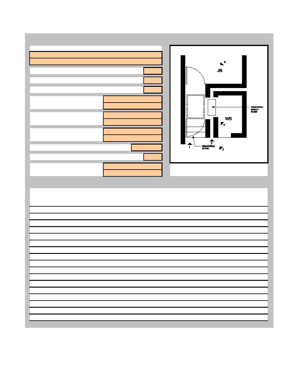
The witness box at one courtroom was entirely independent of the lift enclosure and the judge's bench.
(It appeared that the intent may have been to allow flexibility in its location, but the size and no evidence
of rollers for movement, made it nearly impossible to relocate.) The double millwork half walls, each with
a separate gate, between the lift platform and the witness box made it very difficult to adapt for
accessible requirements. A small metal plate was installed between the lift platform edge and
the witness box, bridging an 8" gap.
A pair of removable risers are placed at the lift, in an elevated position, when accessibility
to the physically disabled is not an issue.
The lift was stable and displayed minimum noise and vibration.
A witness box at another courtroom was located away from the judge's bench, facing perpendicular
to it. This installation included a 3 FT x 5 FT cabinet for equipment location. Only 10 percent of the
cabinet was occupied by lift equipment and the remainder was reserved for other future systems components.
This facility has mechanical ramps for the jury boxes. They are electric powered and project from
retract into space under the elevated platform. The hinged riser concealing the ramp automatically
HDR Architecture, Inc.
Knoxville, TN Installation 5-35


 Previous Page
